

How to Set Up an Automatic Tool Changer on a Desktop CNC
If your desktop CNC doesn’t have the right spindle, air setup, tool holders, and tool positions, an ATC will fail no matter what the software says. I’d set it up in this order: match the spindle and holders, pick a rack or carousel, map each tool to one station, store positions in G53, measure tool lengths from one reference, and dry-run the full cycle at 100–200 IPM before cutting anything.
Here’s the short version:
- Start with hardware, not macros. An ATC-ready spindle, matched holders, dry filtered air, a rack or carousel, and a tool length sensor all need to work together.
- Use one holder per common tool so offsets stay the same from job to job.
- A rack is often the simpler choice on desktop machines. It costs less, takes fewer parts, and is easier to map.
-
Store tool stations in machine coordinates (
G53), not work offsets, so the machine always returns to the same pickup point. -
Follow the same M6 sequence every time: retract, stop spindle, move to pocket, drop tool, pick next tool, clamp, then apply
G43. - Add an air-pressure input so the machine stops if pressure drops during a tool change.
- Check Z offsets and station height with one fixed reference point. Even a small error can throw off cut depth.
- Test with the spindle off first and keep your first runs slow enough to stop fast if something looks wrong.
A few numbers stand out. A basic DIY passive rack can cost about $70 if you already have the spindle. Rack clearance is often at least 1.4 in., and wide tools may need 2.0 in. A common Z adjustment for release and reclamp is 0.005–0.100 in.
Quick comparison
| Setup choice | What I’d expect |
|---|---|
| Rack ATC | Lower cost, simpler motion, more chip exposure |
| Carousel ATC | Smaller footprint, more parts, more setup work |
| Manual workflow | More operator input, more chances for Z-reset mistakes |
| Integrated ATC workflow | Less controller setup, more built-in tool-change handling |
So the main point is simple: ATC setup is mostly about repeatable motion and repeatable offsets. Once those are locked in, multi-tool jobs can run in one program without manual swaps.
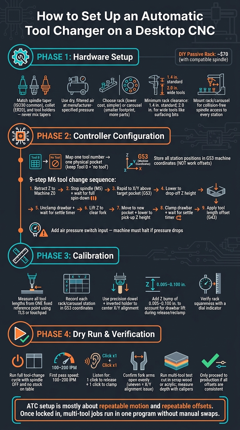
Desktop CNC Automatic Tool Changer Setup: Step-by-Step Process
Step 1: Choose Compatible Tool Holders, Spindle Hardware, and ATC Layout
Match the Spindle, Collet, and Tool Holder System
Start with hardware that makes tool pickup height, retention, and station access repeatable. That means using holders made for your spindle taper. ISO30 is common on desktop ATC spindles, and it's often paired with ER20 collets for standard shank sizes. Keep the holder system matched to the spindle and don't mix tapers.
If you're running a pneumatic ATC spindle, the air supply matters more than people think. Use dry, filtered air at the pressure the spindle maker calls for. Any moisture in the line can lead to uneven drawbar retention.
You'll also want to account for any clamp-related Z shift when setting tool-length offsets. A small shift here can throw off the whole tool change routine.
Choose Tools and Holders for Aluminum, Brass, Wood, and Acrylic
A simple rule goes a long way here: use one holder per often-used tool. When each cutter stays in its own holder, offsets stay put from one job to the next.
Here's a practical starter set for the materials most desktop CNC owners cut all the time:
| Material | Recommended Starter Tool | Why It Works |
|---|---|---|
| Aluminum / Brass | 1/4 in. flat end mill | General clearing and profiling |
| Wood | 1/4 in. downcut or 1/16 in. compression bit | Keeps top edges clean and helps prevent fraying |
| Acrylic / Plastics | O-flute or flat end mill | Improves chip evacuation to reduce heat buildup |
| All materials | 22 mm to 2 in. surfacing bit | Spoilboard leveling and face passes |
| Detail / 3D work | 30° V-bit or 1/8 in. tapered ball nose | Engraving and contoured surfaces |
Machines like the TOPFAB TF500 come with an 8-tool automatic tool changer, which means you can keep several common cutters loaded and skip the constant setup shuffle between jobs.
After you've picked the tool hardware, assign each holder to a fixed station and log those station numbers in the controller.
Place and Number the Rack or Carousel for Safe Access
Mount the rack or carousel where the spindle can reach every station without a collision. The spindle needs enough room to approach and retract cleanly, without clipping nearby holders.
For rack-style setups, leave at least 1.4 in. of slide distance to clear retaining clips. If you're using wide tools, like 2 in. surfacing bits, bump that up to 2 in.. On machines with short Z-travel, a rack offset can help. In some setups, that offset is often 5.5 in., which gives long bits more room and helps prevent them from hitting nearby holders during the approach move.
This quick layout comparison helps:
| Layout | Reach / Travel Impact | Chip Control | Service Access |
|---|---|---|---|
| Front-mounted rack | Uses front table space and cuts usable Y-travel | High exposure to chips unless shielded | Excellent; easy to load and inspect tools |
| Side-mounted rack | Needs more X travel; keeps the table center open | Moderate; can sit away from the main cutting zone | Good; accessible from the side |
| Rear carousel | Minimal table footprint; mounts to the Z-column or head assembly | Best; often enclosed or positioned away from the chip shower | Moderate; may require a dedicated load position |
Before the first dry run, inspect and seat every retaining clip.
"Improperly seated clips can cause ATC accuracy issues." - Sienci Labs
After the hardware is mounted, map each station to a tool number in the controller.
sbb-itb-0a29f4d
Step 2: Configure the Controller, Tool Numbers, and Tool Change Routine
Map Tool Numbers to Physical Stations
Once the rack or carousel is mounted and numbered, line up your CAM tool numbers with the controller's tool table and the machine's physical pockets. In plain English: one tool number should point to one exact pocket, every time.
A lot of controllers let you assign almost any tool number to almost any pocket. That's handy, but it can also get messy fast. The safest move is to keep CAM, the controller, and the rack labels using the same naming system from the start. Also, keep Tool 0 reserved for "no tool".
Store each pocket location in G53 machine coordinates, not G54 work offsets. That matters because G53 is tied to the machine itself. So the spindle goes back to the same spot on the rack no matter where part zero is set.
After that map is locked in, the next piece is the exact tool change sequence: retract, drop, clamp, and apply offsets.
Set Safe Tool Change Positions and Spindle Actions
This is where many desktop ATC crashes happen. A safe tool change uses the same sequence every single time. Skip a step, change the order, or rush a wait period, and things can go sideways in a hurry.
Here's the standard flow:
| Step | Action | Why It Matters |
|---|---|---|
| 1 | Retract Z to Machine Z0 | Clears all fixtures and the rack |
| 2 | Stop spindle (M5); wait for full spin-down | Ensures full spin-down before entering the rack |
| 3 | Rapid to X/Y above the target pocket (G53) | Positions the spindle over the correct station |
| 4 | Lower to the drop-off Z height | Centers the tool groove in the fork |
| 5 | Unclamp drawbar; wait for the settle timer | Lets the pneumatic action fully complete before moving |
| 6 | Lift Z to clear the fork | Releases the old tool cleanly |
| 7 | Move to the new pocket; lower to the pick-up Z height | The pick-up height is often slightly lower than drop-off for better clamp pressure |
| 8 | Clamp drawbar; wait for the settle timer | Confirms the tool is seated before any motion |
| 9 | Apply the tool length offset (G43) | Loads the correct offset from the tool table |
On open systems like Mach4, you'll usually write or edit a macro - often M6Start.mcs - to run those steps in that exact order. On more built-in setups like the TOPFAB TF500, more of that ATC process lives inside the machine, which means less setup by hand.
Before you test anything, add an air pressure switch tied to a controller input. If the compressor is off or the pressure drops below the needed level, the macro should stop at once.
"The air pressure check is a simple pneumatic switch that tells Mach 4 if the air pressure is on and high enough to do a tool change. Without this, the tool will attempt to release and might break the tool fork off." - Corbin Dunn, Corbin's Treehouse
That one check can save you from a broken fork, a dropped tool, or both.
With the routine set, the next issue is how your controller handles it: by macro, or through built-in ATC logic.
Manual vs. Integrated ATC Workflows
The main difference comes down to how much the controller handles for you and how much you still have to script, probe, and double-check yourself. Some setups feel like assembling the plane while flying it. Others handle much more out of the box.
Here's where the work usually shows up on desktop CNC systems:
| Task | Manual (GRBL, Mach3) | Integrated ATC (TF500, PathPilot, Avid CNC) |
|---|---|---|
| Tool mapping | Written by hand into G-code scripts or macros | Visual tool table with T-code-to-pocket linking |
| Pocket positioning | Manual jog to coordinates, record X/Y/Z by hand | Automated "Find Rack" probing sequences using sensors |
| Tool length measurement | Manual Z-probing (G38.2) after every tool change | Automatic measurement via a fixed Tool Length Sensor (TLS) |
| Spindle action | Operator swaps tools and rezeros Z by hand | Pneumatic drawbar release and clamp, controller-triggered |
| Safety checks | Visual confirmation by the operator | Air pressure switches and VFD status monitoring |
| Operator effort | High; the operator has to stay at the machine for every tool call | Low; multi-tool jobs can run unattended |
That split changes the day-to-day experience more than people expect. On manual setups, each tool call means more attention, more checks, and more chances for drift or operator error. On built-in ATC systems, the controller takes care of more of the routine, which makes repeat jobs much easier to manage.
Step 3: Calibrate Tool Length Offsets and ATC Positions
Measure and Store Tool Length Offsets
Now that the tool-change routine is set up, the next job is dialing in the offset values and pickup positions.
Use the TLS or touchpad to store each tool’s Z offset from one fixed reference point. Every tool table entry should include the tool number and its Z offset. Only add XY offsets for 4th- or 5th-axis tools. The main thing is consistency: start with one known reference tool or an empty holder, and make sure every offset ties back to that same baseline.
If one tool is measured from a different starting point, the whole table can drift. That’s when cut depths start coming out wrong, even if everything else looks fine.
Record Rack or Carousel Coordinates for Every Station
Record each rack or carousel station in G53 machine coordinates so the spindle returns to the exact same physical pickup point every time.
For X and Y, use a precision dowel and an inverted holder. Jog X/Y until the taper centers cleanly. This part matters. If the spindle is even a little off-center, you can damage the spindle taper or the holder. Before you lock anything in, make sure the center is dead on.
Set Z so the holder groove sits flush with the fork lip. Then add a 0.005 in. to 0.100 in. Z bump to account for drawbar lift during release and reclamp. Check station height with a dial indicator, and confirm rack squareness before saving the coordinates.
Once those coordinates are fixed, don’t just trust the numbers on screen. Put them to the test with an actual cut.
Verify Repeatability with a Test Cut
Before production, validate the offsets with a multi-tool test cut.
Run the cut in scrap wood or acrylic, then measure depth with calipers. During this first calibration pass, keep tool-change movement speed at 100–200 IPM so you have enough time to hit E-stop if something looks off.
For example, Corbin Dunn described using a 150 IPM "Testing Mode Feed" and a 0.005 in. Z bump during an Avid CNC/Mach 4 calibration.
If the cut depth isn’t consistent, go back and recalibrate the tool offset or station height before moving to Step 4.
Step 4: Dry-Run, Troubleshoot, and Lock In a Reliable ATC Workflow
Run Dry Tests Before Cutting Material
Once your offsets and station coordinates are saved, run the full tool-change cycle with the spindle off and no stock on the table. This is the moment where saved values stop being numbers on a screen and start proving they work in motion.
Start with a basic check:
- Air pressure is on
- Rack sensors respond
- The Tool Length Sensor triggers manually
Run the first pass at 100–200 IPM with Z at a safe clearance height. Then watch the machine closely. Pay attention to Z clearance, station approach, and how the fork opens. If the fork arms open unevenly, you likely have an X/Y alignment problem to fix before running live tools.
Listen, too. You should hear one click to release and one click to clamp. If one of those clicks is missing or the timing sounds off, check the pneumatic switch and air pressure before moving on.
This test is about motion, not guesswork. If the machine misses a station here, it will miss it again in production.
Fix Common ATC Errors Before They Damage Tools or Parts
If the dry run goes sideways, the failure usually points to the cause pretty fast.
| Failure Mode | Likely Cause | Corrective Action |
|---|---|---|
| Tool not fully seated | Low air pressure, fork misalignment, or tool failed to release before Z-lift | Verify pressure, square the fork, and install a pneumatic pressure switch to halt the macro if pressure drops |
| Rack collision during pickup | Incorrect rack offset or slide distance | Recheck rack offset and clearance |
| Bad TLS reading | Dirty TLS or electrical noise | Clean the TLS and use shielded cables |
| Spindle stops in the wrong orientation | VFD or encoder error | Check VFD status and stop delay |
| Controller and spindle out of sync | Tool change interrupted by E-stop | Run Set Tool to resync the controller |
A few habits help avoid wear and ugly surprises. Keep a holder in the collet when the machine is idle to reduce collet fatigue. Check drawbar tension every week, and check it more often if the machine sees heavy use. For the first live-tool test, keep your hand near the E-stop or Cycle Stop button until the machine finishes the sequence cleanly.
Conclusion: ATC Setup Checklist for Repeatable Tool Changes
If the machine clears the dry run, keep those same settings and treat them as your baseline. A repeatable ATC process on a desktop CNC comes down to doing each step in order and checking each one before you move to the next.
Here’s the full setup sequence at a glance:
- Hardware compatibility: Make sure the spindle taper, collet type, and tool holder system match.
- Tool number mapping: Give each physical station its own tool number in the controller, then verify the table before running anything.
- Offset calibration: Measure every tool from the same reference point and save the offsets in the controller.
- Station coordinates: Record each pickup position and confirm alignment with a straight rod and square.
- Dry run: Test every tool change at reduced feed with no stock loaded, while checking clearances, drawbar timing, and sensor response.
On integrated machines like the TOPFAB TF500, this workflow still matters. The machine may handle the sequence, but calibration is what makes multi-tool jobs repeatable.
CNC Build Ep 7: Custom Mach 4 ATC Tool Station Setup! Setting up ATC Tool Pockets / Tool Forks /S30C
FAQs
Can I add an ATC to any desktop CNC?
No. An automatic tool changer (ATC) can't be added to every desktop CNC.
It needs a spindle that can take automatic tool holders, usually paired with a pneumatic power drawbar. You also need a controller that supports ATC macros, tool length offsets, and I/O for sensors or solenoids.
Some hobby machines can work with a passive rack-style changer if you add custom scripting. But many entry-level GRBL-based controllers need major hardware changes or external boards.
How do I know if my spindle and holders are ATC-compatible?
Make sure your spindle supports an automated drawbar. In most setups, that means a pneumatic drawbar with its own air supply and control solenoid. It also needs to work with quick-release holders that fit your taper, like TTS or ER-style holders.
You’ll also want to check that your controller can run M6 macros and has enough I/O for the parts that make tool changes work well every time. That includes solenoids, rack sensors, and tool length sensors for repeatable tool changes.
What should I check first if tool changes are not repeatable?
Check hardware alignment first. Use a straight rod that’s 8–12 in. long to verify that the automatic tool changer is level with the machine table. Also check that the linear bearing sits flush with the main assembly, and make sure the tool holder groove slides into the fork securely, not on top of it.
You’ll also want to confirm that air pressure stays steady within 90–120 psi. If pressure or air volume drops too low, the tool may not seat the way it should.


