

Desktop 5-Axis Tolerances: Limits And Causes
If you want tight parts on a desktop 5-axis machine, the main limit is usually not the brochure spec. It’s heat, tool error, and setup movement.
I’d sum it up like this: most desktop 5-axis jobs land around ±0.002–0.004 in on aluminum and plastics, while softer materials may be looser or tighter depending on the machine and setup. At the high end, some machines publish ±0.0002 in repeatability, but finished-part accuracy can still drift once the spindle warms up, the tool bends, or the part shifts in the fixture.
Before I trust a tolerance claim, I’d look at these three things first:
- Thermal drift: heat from the spindle, axes, and room can shift tool position during a run
- Cutting error: chatter, deflection, and runout can make walls taper and holes cut oversize
- Fixturing error: re-clamping and weak workholding can throw multi-face features out of line
Here’s the short version:
- Soft materials: around ±0.0008 in can be possible on some desktop machines
- General desktop work: about ±0.0020–0.0040 in is a common target
- High-end desktop systems: may publish ±0.0002 in repeatability, but that is not a blanket part-accuracy promise
- Best ways to hold tighter parts: warm up the machine, keep tool stickout short, check runout, and avoid extra setups
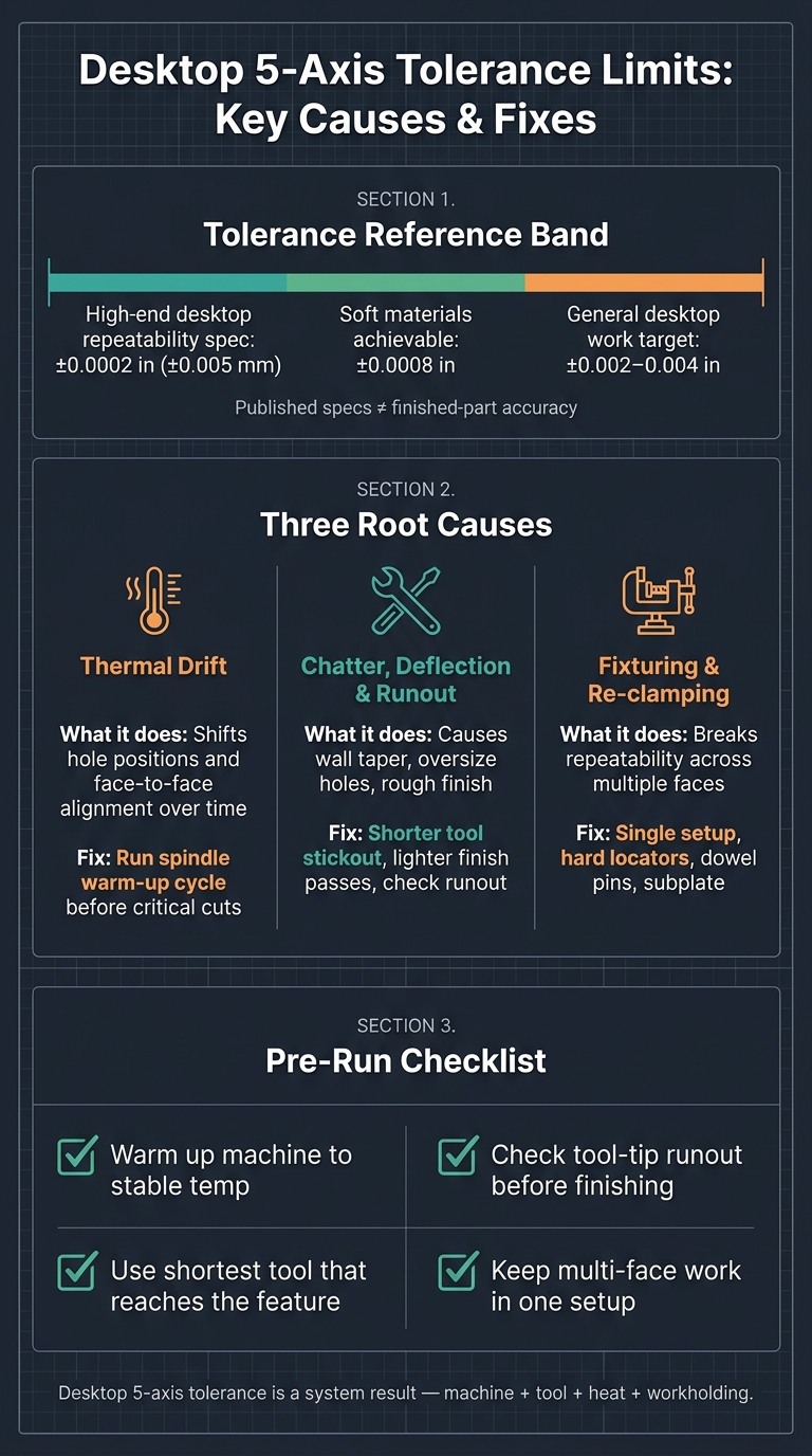
Desktop 5-Axis Tolerance Limits: Key Causes & Fixes
Managing Tolerances in CNC Programming | CNC Skills Webinar
sbb-itb-0a29f4d
Quick comparison
| Issue | What it does to the part | What I’d do first |
|---|---|---|
| Heat and drift | Moves holes and face-to-face alignment over time | Warm up spindle and machine before critical cuts |
| Chatter, deflection, runout | Causes taper, rough finish, and oversize holes | Shorter tools, lighter finish passes, runout check |
| Fixturing and re-clamping | Hurts repeatability across faces | Keep the part in one setup and use hard locating points |
The core point is simple: desktop 5-axis tolerance is a system result. If the machine, tool, temperature, and workholding are all under control, you can hold tight numbers. If one of them slips, the part usually tells you fast.
Problem 1: Drift and thermal change shift the tool off target
Heat from the spindle, axis drives, and the room itself can move a machine off target over time. The shift is slow, which makes it easy to miss in the moment. You run the job, everything looks fine, and then measurement tells a different story. That’s how a part can begin in tolerance and end up out of spec.
On a 5-axis machine, this gets more pronounced. Long periods of motion warm the drives and screws, and that heat changes position even when the control is sending the right commands. In a home workshop or studio, room temperature swings add even more movement as the frame expands or contracts.
How drift and heat appear in finished parts
The clearest sign is hole position shift between the start and end of a job. A hole drilled early in the run may hit the mark, while the same feature made later can move enough to spoil a tight fit.
In 5-axis work, the problem tends to stand out more because the machine keeps rotating and repositioning the part across several faces. If drift creeps in between those rotations, features on different faces may stop lining up cleanly. The result can be a visible step, a mismatch at the edge, or pockets that start to taper as the machine warms up.
How to control thermal error on a desktop machine
Start with a warm-up cycle. Before any precision job, run the spindle through incremental speeds so the machine can settle at a steady operating temperature. It’s a simple step, but it can save a lot of grief later.
Enclosure design also plays a big part. A fully enclosed machine helps block drafts and soften room temperature swings, so conditions stay more steady during long runs. The TOPFAB TF500, for example, pairs an enclosed design with thermoelectric and liquid dual cooling to manage spindle heat.
If your machine doesn’t have automatic tool checks, it’s smart to pause during long jobs and recheck tool position by hand. A short stop in the middle is often a lot cheaper than scrapping a finished part.
Once heat settles down, the next limit usually comes from cutter forces: chatter, deflection, and runout.
Problem 2: Chatter, deflection, and runout distort part dimensions
Once heat drift is under control, the next source of error usually comes from cutter forces and spindle error. On a desktop 5-axis machine, those cutting forces can nudge the tool off its path. And when stickout is long, cuts are too heavy, or the setup isn't stiff enough, chatter, deflection, and runout often show up at the same time.
That’s when dimension issues start to pile up. You may see walls cut oversize, pockets with a slight taper, or holes that miss the target size. The part can also come off the machine with a rough finish or geometry that’s just a bit off.
Chatter and deflection: surface waves, taper, and off-size walls
Chatter is vibration between the cutter and the workpiece. When cutting forces go past what the machine frame or tool can handle, the cutter starts to bounce. And that bounce leaves a clear signature on the part: visible ripples or waves on the surface. It can also push the tool away from the programmed path, which leads to walls that are the wrong size or slightly tapered.
Deflection is different. It’s a bending issue. The longer the stickout, the more the tool can flex under load. That’s why a thin wall may come out uneven from top to bottom, or a deep pocket may taper a bit as the tool bends more with depth. Small-shank tools are hit hardest, so keeping stickout as short as possible is one of the simplest ways to limit this problem.
Machine mass also plays a big part here. A heavier frame does a better job of damping vibration. The TF500 uses a 75 kg industrial-style build, which adds stability for desktop 5-axis work.
Even with a stiff setup, spindle error can still push features out of spec.
Runout: why holes cut oversize and tools wear faster
Runout happens when a tool doesn’t spin perfectly true. Even a tiny amount of eccentricity can make the cutter sweep a slightly bigger diameter than planned. The result is pretty straightforward: oversized holes, poor roundness, and bores that don’t seat well for press fits or bearings.
Runout also loads the flutes unevenly. One flute ends up doing more work than the others, which wears the tool faster and leaves a worse surface finish. Higher RPM can help small tools cut with less force, which reduces runout-related error. A 60,000 RPM spindle supports small-diameter tools and helps keep cutting forces down.
Even machines rated at ±0.005 mm can lose accuracy when rigidity is poor, tool length is too long, or runout creeps in.
Problem 3: Poor fixturing and weak setup cause repeatability errors
After thermal drift and cutter forces, fixturing often sets the tolerance floor. If a part moves or gets re-clamped slightly off position, faces stop lining up and dimensions start to wander. On a desktop 5-axis machine, there’s not much room for those mistakes. In practice, setup errors can pile up faster than machine errors.
How fixturing mistakes affect multi-face accuracy
The most common fixturing issue in multi-face work is using a different reference point for each setup. Those tiny offsets add up fast. A feature machined on face 2 can miss alignment with what was cut on face 1.
Over-clamping thin aluminum or plastic causes another common headache. The part bends during machining, then springs back after unclamping. That leaves finished dimensions off target. This matters a lot with acrylic, nylon, and thin-walled aluminum parts.
Inconsistent re-clamping is just as harmful. If a part is removed and manually clamped again between operations, human error can add more positional error than the machine’s own repeatability. One chip under a jaw or uneven clamp pressure can create more error than the machine can correct.
That’s why fixture choice often decides whether parts stay repeatable or slowly drift.
Workholding practices that improve repeatability
The fix is pretty straightforward: keep the part in its first setup as much as possible. True simultaneous 5-axis machining can cut multiple faces in one setup, which reduces repositioning error. Modular fixturing also helps keep setups consistent from job to job.
When re-clamping can’t be avoided, a few habits make a big difference:
- Use hard stops, dowel locators, or a subplate to bring the part back to the same datum
- Support thin parts with backing material
- Keep tool offsets consistent during swaps
- Use vision-assisted tool setting to keep offsets steady after tool swaps
This is one of those shop-floor issues that sounds small on paper but shows up fast in finished parts.
Solutions and conclusion: Holding Tighter Tolerances Consistently
The fix for all three issues comes down to the same few habits: control heat, cut tool error, and stop setup movement from creeping in.
A short checklist for tighter desktop 5-axis parts
Use this checklist before any tight-tolerance run.
- Warm up the machine and let the spindle reach a stable operating temperature before cutting critical features.
- Check tool-tip runout before finishing passes.
- Use the shortest tool that can reach your feature, and take lighter finishing passes on hard materials.
- Keep multi-face work in a single setup whenever possible.
Key takeaways on tolerance limits and root causes
Desktop 5-axis tolerances don't come down to one spec on a product page. They depend on the whole system working together.
High-end units like the TOPFAB TF500 claim a positioning repeatability of ±0.005 mm and rotary accuracy of ±10 arcsec. They also use thermoelectric and liquid cooling to help maintain precision during long operations.
FAQs
What tolerance can I realistically expect?
On a desktop 5-axis machine, a realistic positioning repeatability figure is about ±0.005 mm. High-end desktop units such as the TOPFAB TF500 typically rate rotary accuracy at ±10 arcsec, which helps keep part geometry consistent.
That said, actual tolerances can shift in day-to-day use. Machine deflection, thermal expansion during operation, and fixturing quality all play a part.
Why is repeatability different from part accuracy?
Repeatability is a machine’s ability to return to the same position, or produce the same result, the same way over many cycles. Accuracy is how closely the finished part matches the intended dimensions in the digital design.
Here’s the key difference: a machine can be very repeatable and still be inaccurate. If it keeps landing on the same wrong spot every time, it’s consistent - but still off target.
So while repeatability is about consistency, accuracy is about correctness. To get high accuracy, you need both repeatability and proper calibration.
How do I know if heat, tool error, or fixturing is the main problem?
Look at how the part differs from the digital model. Heat usually shows up as gradual drift during long runs or more complex cycles. Fixturing often shows up as inconsistencies during multi-angle cuts. Tool error or deflection usually appears as chatter or a rough surface finish.
On the TOPFAB TF500, the dual-cooling system helps cut heat-related drift, simultaneous 5-axis motion helps cut fixturing issues, and the built-in HD camera helps monitor tool-related problems.


