

5-Axis Geometry Refinement Workflow Summary
If the geometry is bad, the cut will be bad. I’d boil this workflow down to four steps: bring in the model, check it for defects and machine access, fix the surfaces, then send it to toolpaths.
Here’s the short version: a part can look finished in CAD and still fail on the machine because of open meshes, bad edges, tight corners, or tool-holder collisions. This workflow fixes those issues before cutting starts, which helps cut scrap, setup delays, and wasted tool time. On a desktop 5-axis machine like the TOPFAB TF500, that matters even more because the machine can move through ±360° on the C-axis and -110° to +110° on the A-axis, so geometry errors can turn into motion and clearance problems fast.
What I’d focus on first:
- Intake: Turn photos, sketches, text prompts, STL, or OBJ files into editable 3D geometry.
- Checks: Find non-manifold edges, open boundaries, flipped normals, self-intersections, thin walls, and tight radii.
- Refinement: Close gaps, smooth rough areas, and change small features so cutters can reach them.
- Handoff: Set part orientation, split roughing vs. finishing, and run simulation before cutting.
A few hard numbers stand out:
- 60,000 RPM spindle
- ±0.005 mm positioning repeatability
- ±10 arcsec rotary accuracy
- 8-tool automatic tool changer
For me, the main point is simple: clean geometry leads to fewer machine-side surprises, better first-pass cuts, and steadier short-run output. The rest of the article explains how each step helps get there.
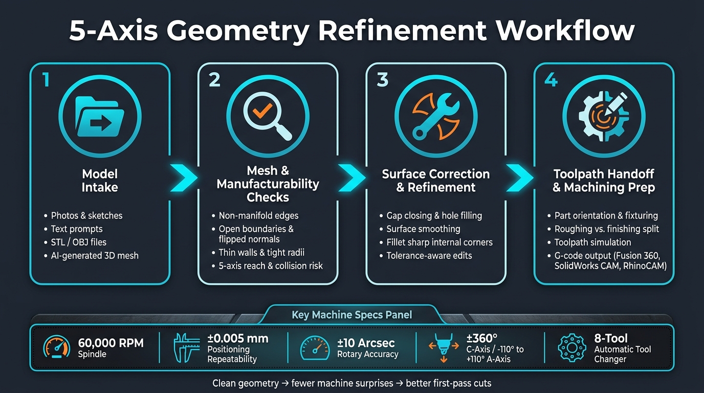
5-Axis Geometry Refinement Workflow: From Raw Input to First Cut
1. Model Input and Geometry Intake
The workflow starts by turning raw inputs into machinable geometry. On a desktop 5-axis machine, that input might come from photos, hand sketches, text prompts, or imported STL or OBJ meshes.
Accepted input types and how they become editable geometry
Photos, hand sketches, and text prompts go through the intake stage, where the system builds a first-pass 3D model. AI-driven workflows can also turn 2D inputs into 3D meshes and suggest early 5-axis roughing toolpaths. If you import STL or OBJ meshes, they skip the generation step, but they still need repair and review before machining.
What desktop 5-axis users need at the intake stage
For desktop 5-axis users, intake is more than just loading a file. The model has to be accurate enough for repair work and toolpath planning later on. You also need to check the intended scale before machining starts.
It also helps to define the target material early. That lets the system pick cutting parameters that fit the job. Set the workflow for aluminum, stainless steel, engineering plastics, or composites so the rest of the process stays clean and organized.
Once intake is done, the workflow moves to mesh analysis and manufacturability checks.
sbb-itb-0a29f4d
2. Mesh Analysis and Manufacturability Checks
After intake, check the model for defects, reach, and collision risk before toolpath generation. This step helps catch problems early, when they’re still easier to fix.
Detecting defects that block machining
Common defects include non-manifold edges, open boundaries, flipped normals, self-intersections, and uneven triangle density. Any of these can get in the way of reliable 5-axis machining.
Modern AI-driven workflows handle this by automatically generating watertight meshes and running fit and tolerance checks. Then the model is screened for thin walls, small holes, and tight internal radii against tool size, reach, and machine limits. If it clears those checks, the workflow moves to surface correction.
Screening for 5-axis access, reach, and collision risks
The next step is to verify axis access and holder clearance. The workflow checks undercuts, deep cavities, and holder clearance before toolpaths are generated.
Automated interference checks and 3D simulation flag possible collisions between the tool holder and part features during complex 5-axis motion. On the TOPFAB TF500, the ±360° C-axis and -110° to +110° A-axis make it easier to verify reach and cut down on re-fixturing. That gives the team a clear green light before toolpath handoff.
3. Surface Correction and Refinement
Once manufacturability checks are done, the next step is cleanup. This part of the workflow fixes small defects and adjusts the model so the cutter can actually get in and do its job. That matters because the target isn't a perfect-looking model on a screen. It's a model that cuts cleanly on a desktop 5-axis machine.
Repairing gaps, smoothing transitions, and restoring surface continuity
Common fixes include hole filling, gap closing, and smoothing rough mesh areas. These repairs aren't just cosmetic. Even small gaps can cause CAM software to read solid and empty regions the wrong way, which can lead to bad toolpaths or outright failure. After those openings are closed, the surface should be smoothed so cutter engagement stays steady.
Surface continuity also plays a big role in finish quality. When one patch meets another too abruptly, you can end up with visible ridges and uneven cutter contact, especially on curved or organic shapes. AI-assisted workflows can smooth those transitions without changing the intended form.
Adjusting geometry for machinability without losing part intent
Repairing defects is only half the job. In many cases, the geometry also needs small, deliberate edits so it can be machined cleanly. That often means adding fillets to sharp internal corners, easing harsh wall transitions, or opening tight features so the cutter can reach them.
If an internal corner is tighter than the cutter can enter, the model needs a fillet or a slightly more open feature that fits the tool envelope. Small-radius tools can only work if the corner matches their reach. The same idea applies to fit features and other critical dimensions: they need to stay intact even while the model is being cleaned up.
This type of refinement helps speed up prototype iteration and improves repeatability in short-run production. AI-assisted correction can automate mesh cleanup and tolerance-aware edits, but users should still review the result before machining. The TOPFAB TF500 outputs standard G-code, so manual tuning can still happen in existing CAM tools when needed.
Once refinement is complete, the model is ready for toolpath strategy and machining setup.
4. Toolpath Handoff and Machining Preparation
With the geometry cleaned up and checked, the next step is toolpath strategy. This is where setup choices, tool selection, and simulation come together. It’s also the point where small mistakes from earlier in the process can turn into lost shop time.
From refined model to 5-axis toolpath strategy
The first call is part orientation. On a 5-axis machine, the way the part sits in the fixture decides which features you can reach in one setup. Get that right early, and you can avoid repositioning mistakes later.
After orientation is locked in, the workflow usually breaks into two stages:
- Roughing uses larger end mills to remove stock fast.
- Finishing uses smaller cutters, often small tapered ball nose cutters, to hold fine surface detail on curved or contoured geometry.
Before cutting starts, run one last toolpath simulation. That’s the handoff point where setup decisions turn into cut-ready toolpaths.
Where a desktop system like TOPFAB TF500 fits in this workflow
On a desktop 5-axis system like the TOPFAB TF500, this handoff stays tight and simple. Its true simultaneous 5-axis motion, with a ±360° C-axis and -110° to +110° A-axis, supports complex parts in a single clamping operation, which cuts down on repositioning errors.
The 60,000 RPM spindle supports fine finishing passes. And ±0.005 mm positioning repeatability plus ±10 arcsec rotary accuracy help keep the refined geometry intact through the last toolpaths.
The AI toolpath workflow also cuts CAM setup work. It can generate the model, process logic, toolpaths, and simulation automatically. If your team already has a CAD/CAM pipeline, the TF500 accepts standard G-code from Fusion 360, SolidWorks CAM, and RhinoCAM.
A few machine features also help smooth out the jump from roughing to finishing:
- 8-tool automatic tool changer
- Vision-assisted wear detection
- Built-in HD camera
- Dual-vision automatic tool setting
Together, those features support automatic roughing-to-finishing transitions and help verify setup before the cut begins.
Compared with 3-axis desktop machines, the TF500 keeps refined geometry inside a true 5-axis workflow with fewer setups.
Conclusion: What This Workflow Delivers in Practice
Put all of these stages together, and rough geometry turns into parts you can actually machine. Run the workflow from start to finish, and the payoff is simple: fewer surprises at the machine, less time spent fixing geometry later, and better first-pass results. Each stage cuts risk before the next one begins.
That shows up most clearly when a small defect could turn into a failed cut. The biggest win is finding errors before machining starts. Catching a non-manifold edge or a collision risk during the analysis stage takes little time. Catching the same problem in the middle of a cut can cost material, tooling, and setup time. AI checks catch defects before cutting.
For short-run work, this same workflow helps keep repeated parts consistent. Repeatability matters most in short-run production. On the TOPFAB TF500, those controls support consistent short-run output.
In plain terms, this workflow cuts the gap between design intent and a part you can use. AI shortens the path from design intent to finished part - exactly what prototype work and short-run production need.
FAQs
How do I know if my model is ready for 5-axis machining?
Your model is ready once it’s been turned into a compatible 3D mesh and verified in a toolpath simulation.
With the TOPFAB TF500, the AI workflow can build a 3D model and matching 5-axis toolpaths from a photo or sketch. From there, you can review everything, make edits, and check the setup before cutting. It also accepts standard G-code from Fusion 360, SolidWorks CAM, or RhinoCAM.
Which geometry problems are most likely to cause a bad cut?
The most common cause is repositioning error. When a part has to be moved or clamped more than once to reach complex geometry, small alignment shifts can creep in. Those shifts often lead to structural inaccuracies and, from there, bad cuts.
In the TF500 workflow, simultaneous 5-axis motion in a single setup cuts down on those errors. Its AI-assisted 3D mesh and toolpath generation also helps flag geometry inconsistencies before cutting starts.
When should I edit the model instead of changing the toolpath?
Edit the 3D model when the issue is in the geometry itself. That includes walls that are too thin, draft angles that block tool access, or features the spindle can’t reach even with simultaneous 5-axis motion.
Change the toolpath only when the geometry is sound but the machining strategy needs work. That usually means adjusting stepovers, depths of cut, or approach angles. On the TOPFAB TF500, AI-generated meshes can be reviewed and refined before toolpath generation.


