

7 In-Process Quality Checks for Small-Batch CNC
One bad part in a 5-part CNC run can wipe out 20% of the job. That’s why I’d treat in-process checks as part of the cut, not something I do only after unload.
Here’s the short version: if I want to keep scrap down in a small batch, I check setup, first-pass features, tool wear, surface finish, hole size and position, fixture hold, and final in-machine results. That order helps me catch errors while the part is still clamped, when I still have a shot to fix them.
What this article covers, in plain terms:
- Stock alignment and work offsets before the first cut
- First-off dimensions right after the first critical feature
- Tool condition before wear turns into drift
- Surface finish as an early warning sign
- Hole size and hole location during the batch
- Fixture movement after roughing and vibration
- Final in-machine verification before unclamping
If I had to sum it up in one line, it would be this: check early, check in-machine, and don’t wait until the batch is done to find a problem.
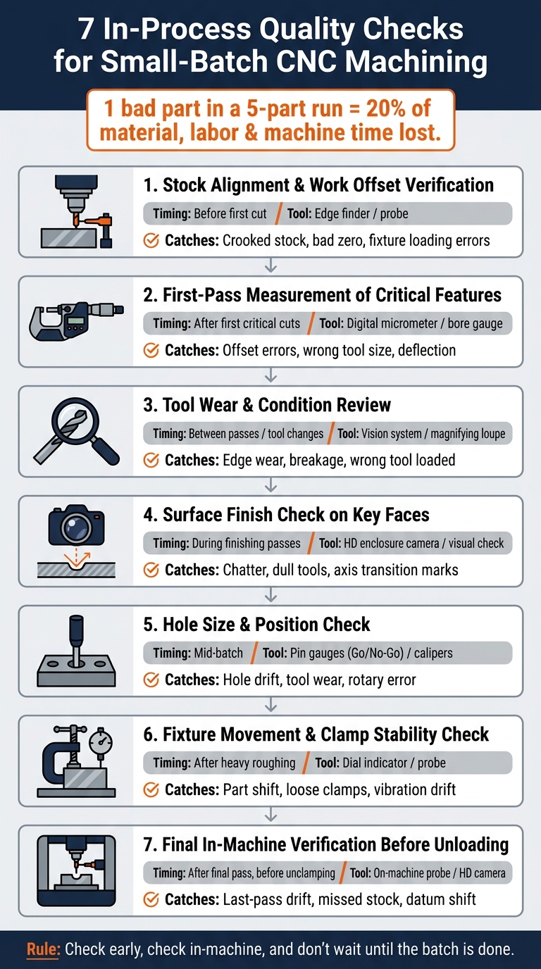
7 In-Process Quality Checks for Small-Batch CNC Machining
In-Process Laser Checks CNC Parts while Machining
sbb-itb-0a29f4d
Quick Comparison
| Check | When I’d Do It | What It Helps Catch |
|---|---|---|
| Stock alignment | Before cutting | Crooked stock, bad zero, fixture loading errors |
| First-pass measurement | After first critical cuts | Offset issues, wrong tool size, deflection |
| Tool condition review | Between passes or tool changes | Wear, breakage, wrong tool loaded |
| Surface finish check | During finishing | Chatter, dull tools, axis marks |
| Hole size and position | Mid-batch | Hole drift, tool wear, rotary error |
| Fixture stability check | After heavy roughing | Part shift, loose clamps, vibration drift |
| Final in-machine check | Before unloading | Last-pass drift, missed stock, datum shift |
For small-batch work, that simple routine can save material, machine time, and delivery dates. The rest of the article walks through each check and when I’d use it.
Why In-Process Checks Matter More in Small-Batch CNC
In a five-part run, one bad part wipes out 20% of your material, labor, and machine time. And here’s the part that stings: setup and programming time don’t get smaller just because the batch is small. Those fixed costs are spread across fewer parts, which pushes the cost per part higher.
That’s why in-process checks matter so much in small-batch CNC. If you catch a size problem or tool issue on part 1 or 2, you still have most of the batch left to save. The first-pass check is your earliest shot at protecting the run.
In small batches, check critical features as soon as they’re cut. Waiting until the end is a gamble, and in a short run, that gamble gets expensive fast.
Mixed metric and imperial dimensions on the same print can also trip people up. It doesn’t take much - a wrong unit at one checkpoint can throw off the whole inspection. Each check needs to match the print’s units exactly. And even when the units are right, setup accuracy still comes down to machine stability and fixturing.
Desktop 5-axis machines can cut repositioning error, which helps. But they don’t remove the need for in-process checks. Start with stock alignment and work offsets before you trust anything downstream.
1. Stock Alignment and Work Offset Verification
Check Timing
Run this check after you clamp the stock and before the first cut.
Critical Feature Focus
The point of this step is simple: make sure the machine’s coordinate zero lines up with the actual stock edges, and make sure the stock is sitting square to the machine axes.
If the blank is crooked or zero is off, the problems show up fast. You’ll see holes in the wrong spot, uneven chamfers, or faces that don’t land where they should. On a single-setup 5-axis part, one bad origin throws every move off.
Recommended Inspection Tools
For manual setups, an edge finder gives you a solid starting point. If your machine has a built-in vision system, like the TOPFAB TF500, that system can help locate zero without manual offset entry. Use auto Z-probing to verify top-surface zero.
Typical Failure Caught
This check helps catch crooked stock, the wrong zero location, and fixture misloading. On a high-repeatability machine like the TOPFAB TF500, offset verification can catch small setup mistakes before cutting starts. After zero is confirmed, measure the first cut before the run moves on.
2. First-Pass Measurement of Critical Features
Check Timing
Once stock alignment and offsets are in place, cut the first part and inspect it before moving on. Do this right after the first passes. That early check helps confirm offsets, coordinates, and toolpath accuracy before the rest of the batch is on the line.
Critical Feature Focus
Start with the features that have the tightest tolerances, especially datums and reference geometry. If one of those is even slightly off, that error can carry through every part that comes after it.
Recommended Inspection Tools
Use an inspection tool that fits the tolerance you need to hold. For tight-tolerance features around ±0.005 mm, a high-resolution digital micrometer or bore gauge is the right call. Calipers just aren't precise enough for checks that tight.
For curved surfaces, undercuts, and other angled or recessed features, on-machine cameras help you inspect the first pass as it happens.
The vision system can identify tool type and wear in real time and support automatic finishing changes.
On machines like the TOPFAB TF500, built-in cameras let you watch the first-off part from a distance and step in fast if the toolpath or setup looks wrong.
Typical Failure Caught
A first-pass measurement usually catches four common issues:
- Work offset errors
- Wrong tool diameter or tool wear
- Tool deflection
- Stock misalignment that got past the setup check
| Problem | What You See on the Part | Fix |
|---|---|---|
| Work offset (WCS) error | All features shifted in one direction | Pause and re-zero the Work Coordinate System |
| Tool wear or wrong diameter | Feature consistently oversized or undersized | Verify the tool in the ATC and update the tool table |
| Tool deflection | Tapered walls or dimensional drift | Reduce feed rate or use a shorter tool |
| Stock misalignment | Features misaligned with stock edges | Re-fixture the part and re-probe datums |
If the first part is off, stop the run and fix the root cause before anything else gets cut.
3. Tool Wear and Tool Condition Review
Check Timing
Once the first-off part is in tolerance, check the cutter again before the next passes. Do this during tool changes and right before finishing passes. A worn roughing tool can pass defects into the rest of the batch, so this step matters more than it might seem at first.
Critical Feature Focus
Put the most attention on the tools cutting your tightest features and hardest geometry. Tight-tolerance parts react fast to wear, and undercuts or curved surfaces often show trouble first.
Watch for:
- Size drift
- Chatter
- Rougher edges
Those small warning signs can snowball fast if the batch keeps running.
Recommended Inspection Tools
Vision-based systems are the best fit for in-process tool checks. On the TOPFAB TF500, the vision system can detect tool type and wear, and the camera can help spot breakage or odd chip flow.
Use the camera to confirm tool condition before the batch moves on. If vision detection isn't available, inspect the cutter by hand and verify the tool table before the next finishing pass. It’s a simple check, but it can save a lot of scrap.
Typical Failure Caught
This check helps catch edge wear, wrong tools, and breakage before the next part is cut.
| Failure Type | Early Sign | Action |
|---|---|---|
| Excessive edge wear | Size drift or rougher edges | Replace the tool before the next finishing pass |
| Wrong tool loaded | First cut comes out oversized or undersized | Verify the tool in the changer and correct the setup |
| Broken tool | Sudden surface defect or vibration | Stop the run and replace the tool |
If wear shows up in the cut, move right away to surface finish and size checks.
4. Surface Finish Check on Key Faces
Check Timing
Once tool wear is in check, surface finish is often the next place trouble shows up. Check surface quality as soon as the finishing tool loads, before the final pass runs. A small shift in finish can point to tool wear or axis drift before the part slips out of tolerance.
Critical Feature Focus
Pay close attention to mating surfaces, sealing faces, and cosmetic exteriors on complex 5-axis parts. On simultaneous 5-axis work, inspect axis transition zones for witness marks or small ridges. Those areas tend to tell the story early.
Recommended Inspection Tools
Use the enclosure camera to look for chatter lines, tool dulling, or changes in reflection without opening the machine. On the TOPFAB TF500, the HD camera lets you inspect without opening the enclosure. Treat the built-in camera as a fast go/no-go check before the final pass.
Typical Failure Caught
| Failure | Early Sign | Action |
|---|---|---|
| Tool wear / built-up edge | Dull, streaky, or uneven reflection | Replace the tool before the finishing pass |
| Chatter | Ripple pattern on flat or curved faces | Adjust spindle speed |
| Axis transition mark | Faint ridge at a blend point | Verify 5-axis calibration and toolpath |
| Heat-related finish loss | Rough or inconsistent finish on hard metals | Check coolant before the next pass |
If the finish changes, recheck hole size and feature location before unloading. If finish quality shifts, verify hole size and position before the batch continues.
5. Hole Size and Position Check
After the finish check, verify hole size and hole location before the batch moves on.
Check Timing
Run this check mid-batch. That gives you a chance to catch hole drift before the rest of the run gets cut.
Critical Feature Focus
Start with holes that act as alignment points or mating features. Focus on two things:
- Hole diameter
- Center-point location against the work offset
On 5-axis parts, watch compound-angle holes and undercut-face holes a little closer. That’s usually where rotary error shows up first.
Recommended Inspection Tools
Use probing to verify hole depth and location against the work offset. On the TF500, vision-based tool setting helps keep tool length and diameter compensation consistent.
Typical Failure Caught
| Failure | Cause | Action |
|---|---|---|
| Hole undersized from tool wear | Tool wear reducing the effective cutting edge | Replace the tool and rerun the hole operation |
| Hole location drift | Thermal expansion or fixture shift mid-batch | Recheck the work offset and clamp stability |
| Compound-angle hole misalignment | Rotary axis calibration error | Check rotary calibration |
| Wrong-size hole | Incorrect tool loaded | Verify the tool before drilling |
If hole position shifts, recheck clamp stability and fixture movement next.
6. Fixture Movement and Clamp Stability Check
Hole drift often starts with clamp loss, not tool error. So if hole location begins to wander halfway through a batch, check whether the part moved in the fixture.
Check Timing
Do this check mid-batch, right after heavy roughing. That's usually when clamps are most likely to work loose.
Critical Feature Focus
Look at features machined early in the run, especially datum holes and previously finished faces. These are usually the first spots where a workholding shift shows up.
On 5-axis parts, even a small fixture shift can knock compound-angle features out of position. It doesn't take much.
Recommended Inspection Tools
Use the built-in HD camera to watch the fixture and stock in real time. Then probe a known datum mid-batch. If it no longer matches the original work offset, the fixture moved.
At speeds up to 60,000 RPM, vibration can loosen clamps and shift the part, so both checks matter.
Typical Failure Caught
| Failure | Cause | Action |
|---|---|---|
| Hole mislocation mid-batch | Workpiece shifted between tool changes | Re-clamp, re-probe work offset, rerun affected operations |
| Chatter on finish passes | Insufficient clamping force during high-speed cuts | Tighten clamps, reduce feed rate, recheck surface finish |
| Dimensional drift across parts | Vibration gradually loosening fixture over the run | Stop batch, re-clamp, verify datum before continuing |
| Repositioning error | Manual re-setup in multi-step workflow | Switch to single-setup 5-axis approach where possible |
If the part is still stable, move to the final in-machine check before unloading.
7. Final In-Machine Verification Before Unloading
Once fixture stability is confirmed, do one last in-machine check before unloading the part.
Run this check after the final machining pass and before unclamping. The goal is simple: make sure the part stayed put through the last pass and that the final operation didn’t add any new drift after your setup, tool, and clamp checks already cleared.
Check Timing
Run it after the final machining pass, before releasing the clamps.
Critical Feature Focus
Focus first on features machined in a single setup, especially complex geometries, undercuts, and curved surfaces. These are often hard to measure well once the part comes off the machine.
Also verify tight-tolerance features before unclamping, including parts held to ±0.005 mm. If something moved, this is your last clean chance to catch it while the part is still in place.
Recommended Inspection Tools
Use the enclosure camera for a final visual sweep. Look for missing material, incomplete cuts, or anything that looks off.
Then use the probe to check the primary datum and one critical feature. This helps confirm that the coordinate system held through the final pass.
Typical Failure Caught
| Failure | Cause | Action |
|---|---|---|
| Dimensional drift on final feature | Tool wear during finishing pass | Replace the tool and re-run the finishing operation before unclamping |
| Missed stock on a curved surface | Repositioning error or axis lag | Re-run the affected pass while the part is still clamped |
| Datum shift during the run | Part movement or setup instability | Re-probe the datum, adjust the offset, and verify the critical dimensions |
| Broken tool not flagged mid-run | No vision-based tool check after ATC | Inspect the feature with the camera and re-run with the confirmed tool |
How to Apply the 7 Checks During a Real Batch
Run the seven checks in sequence so you catch problems before they spread across the whole batch. The order matters: setup, first-off, tool condition, finish, holes, fixturing, and final probe.
Before Cutting: Confirm Setup, Stock, and Offsets
Before the spindle starts, check that the stock size matches the drawing, the material sits flat against the fixture, and the work offsets point to the right datum. A small setup miss here can throw off every part that follows.
If you're using a machine like the TOPFAB TF500, review the AI-generated toolpath on the touchscreen before you begin. If a roughing pass doesn't line up with the stock size, fix it before cutting.
After Initial Passes: Measure First-Off Features
Pause the program once the first critical feature is cut. Measure that feature against the print before any finishing passes start.
If it's out, adjust the tool offset before the run moves on. That's the moment to fix the issue - while it's still one bad feature, not ten bad parts.
During the Run: Monitor Tool Condition and Surface Finish
Between parts, keep an eye on tool wear and any change in surface finish. Use the enclosure camera to watch chip evacuation and the surface texture on key faces.
On machines with vision-assisted tool recognition, like the TF500, vision feedback can flag worn tooling before the next part starts. That gives you a chance to swap the tool before finish quality slips.
Mid-Batch: Recheck Holes, Feature Location, and Fixturing
On longer runs, repeat spot checks at a fixed interval. Focus on a few things that tend to drift first:
- Check hole diameters with a plug gauge
- Verify feature location from the datum
- Check clamp tightness by hand
Chip buildup or a slight fixture shift can affect later parts, even when the first ones looked fine.
Before Unloading: Complete Final In-Machine Verification
Before you release the clamps, probe the primary datum and one critical feature. If a dimension is out of tolerance, re-run the finishing pass while the part is still in position.
That simple step can save a part that would otherwise be scrap.
Use a Simple Inspection Sheet Tied to the Print
Record each check as it happens so the batch stays traceable. Number the critical features on the drawing, then use those same reference numbers on the inspection sheet. That way, there is no guesswork about what was checked.
| Field | Example Entry |
|---|---|
| Date | 07/23/2026 |
| Part Count | Part #3 of 10 |
| Drawing Ref # | Ref #10 |
| Feature Description | Main Bore Diameter |
| Tolerance | 15.000 mm ±0.005 mm |
| Measured Value | 15.002 mm |
| Tool Notes | Tool #3, 6 mm End Mill, New |
| Pass/Fail | Pass |
Keep one sheet per batch. Log the date in MM/DD/YYYY format, the tool number used for each critical cut, and a Pass/Fail result. If a check fails, add a short note on what action you took, such as offset adjusted, tool replaced, or pass re-run.
Desktop 5-Axis Features That Support These Checks
These checks are much easier when the machine helps you confirm the setup, keep an eye on tool wear, and verify the part before you take it out. On a desktop 5-axis CNC like the TOPFAB TF500, clear visibility, probing, tool tracking, and stable fixturing help cut setup drift and make in-process checks faster.
Probing, Cameras, and On-Machine Visibility
The TF500’s HD camera and 7-inch touchscreen make setup checks, stock verification, and final in-machine inspection faster, all without opening the enclosure. That saves time, but it also keeps the process more controlled since you’re not stopping to peek inside every few minutes.
Once the setup is locked in, the next thing to watch is the tool itself.
Automatic Tool Changes and Tool Tracking
The 8-tool automatic tool changer and vision-based tool tracking help cut handling errors and keep roughing and finishing checks tied to the same setup. That matters more than it might seem at first glance. If tools are being swapped by hand or loaded inconsistently, small mistakes can snowball into bad surface finish or missed dimensions.
Of course, steady tooling only helps if the part stays put.
Modular Fixturing and Enclosed Setup Stability
Modular fixturing helps keep part location consistent across small batches. That’s a big deal when you’re running the same job more than once and don’t want to chase alignment each time.
The enclosed design keeps chips contained, and the machine’s 75 kg frame and ±0.005 mm repeatability support repeatable small-batch runs. In plain terms, the machine is built to hold its position well enough that your checks mean something from one part to the next.
Remote Monitoring for Check Timing
Remote monitoring lets you check job progress without standing at the machine the whole time, so you can come back for first-off and final verification when it makes sense. Instead of babysitting the cycle, you can time your checks better and step in when the part is actually ready for review.
Quick Reference: Measurement Tools and Checkpoints
Use this quick reference after the seven checks above when you need to pick the right tool FAST.
Best Tool for Each of the 7 Checks
Use this table as a fast tool-to-check guide. Think of it as the batch-run version of the checklist.
| Check | Best Tool | What It Verifies | When to Use |
|---|---|---|---|
| 1. Stock Alignment | Edge finder / dial indicator / probe | Work offsets and part squareness | Before the first cut |
| 2. First-Pass Dimensions | Calipers / micrometers | First-pass dimensions | After the first critical feature |
| 3. Tool Condition | Vision system / magnifying loupe | Wear or breakage | Between tool changes or mid-batch |
| 4. Surface Finish | HD camera / visual check | Finish quality | During finishing passes |
| 5. Hole Size & Position | Pin gauges (Go/No-Go) / calipers | Diameter accuracy and center location | Immediately after drilling or boring |
| 6. Fixture Stability | Dial indicator | Fixture shift | After heavy roughing passes |
| 7. Final Verification | On-machine probe / HD camera | Final geometry | Before unloading the part |
Match the Measuring Method to the Tolerance
Here’s the rule: use a gauge with resolution at least 10x finer than the tolerance. If your tolerance is ±0.05 mm, your measuring tool should read to 0.005 mm.
A simple way to match the tool to the job:
- Use calipers for loose fits
- Use micrometers or bore gauges for tight features
- Use pin gauges for holes
Match tool resolution to tolerance before the next batch starts.
Conclusion
Put together, these checks turn in-process inspection into a batch routine you can repeat from run to run. More importantly, they catch errors before unload.
Keep the routine simple and stick to the same sequence every time: verify setup, measure first-off features, watch tool condition, check finish, confirm holes, recheck fixturing, and probe before unload.
Desktop 5-axis systems like the TOPFAB TF500 make that process easier to follow. Machines like the TOPFAB TF500 can speed up these checks with repeatable positioning, vision-based tool monitoring, and remote visibility. Treat the fixture as your last quality-control station. Check early, check in-machine, and unload only after the part is proven.
FAQs
Which in-process check should I prioritize first?
Prioritize stock alignment first. Proper workpiece orientation sets the stage for every check that follows, especially in simultaneous 5-axis machining, where geometry and toolpath accuracy depend on the initial setup.
On machines like the TOPFAB TF500, it makes sense to check alignment right away so small setup issues don’t snowball into cumulative errors. After that, move to first-pass measurement, tool wear review, and surface finish assessment.
How often should I repeat these checks in a small batch?
In a small-batch run, how often you check depends on two things: machine stability and part complexity. Start with the basics first: verify the initial alignment, then confirm your first-pass measurements.
On systems like the TOPFAB TF500, automated monitoring can cut down on frequent manual checks. It tracks tool type and wear in real time and helps reduce errors that come from manual repositioning.
What measuring tools are best for tight-tolerance CNC parts?
The search results don’t name a single best measuring tool for tight-tolerance CNC parts. Instead, they focus on the TOPFAB TF500, which offers positioning repeatability of ±0.005 mm along with vision-based automatic tool recognition and wear detection.
For tight-tolerance work, shops usually rely on standard metrology tools to check finished dimensions against CAD models. That often includes:
- Calibrated digital micrometers
- Calipers
- Dial test indicators
In plain terms, the machine’s repeatability matters, but so does how you verify the part after machining. That’s where these measurement tools come in.


