

Multi-View Images vs Single Image for 3D CNC
If I need clean geometry for acrylic or metal, I would pick multi-view. If I need a fast draft for a wood relief, I would use a single image.
That is the core idea. One photo is faster, but the system has to guess more of the shape. More photos take more setup, but they cut down on guesswork and usually lead to safer machining. In this article, I’m looking at accuracy, machine risk, material fit, hidden surfaces, undercuts, mesh cleanup, and 5-axis machining - not just whether the model looks good on screen.
Here’s the short version:
- Single image works best for shallow carvings, portraits, and other front-facing parts
- Multi-view is a better fit for full 3D forms, undercuts, and parts that must fit other parts
- Wood can handle small model errors better than other materials
- Acrylic shows shape errors fast through chipped or frosted edges
- Metal gives you the least room for error and often needs mesh review plus CAD help
- 5-axis CNC matters when I need to cut angled faces and undercuts in one setup
- Photo overlap of 60% to 80% and stable, diffuse light matter a lot for multi-view work
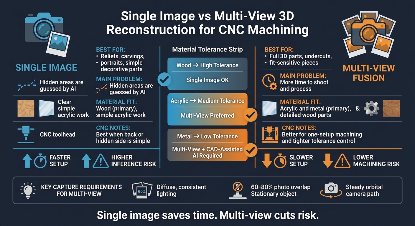
Single Image vs Multi-View 3D Reconstruction for CNC Machining
Quick Comparison
| Method | Best For | Main Problem | Material Fit | CNC Notes |
|---|---|---|---|---|
| Single image | Reliefs, carvings, portraits, simple decorative parts | Hidden areas are guessed | Wood first; some simple acrylic work | Best when the back or hidden side is simple |
| Multi-view | Full 3D parts, undercuts, fit-sensitive pieces | More time to shoot and process | Acrylic and metal; also better for detailed wood parts | Better when I need one setup and tighter control |
So if I had to put it in one line: single-image saves time, multi-view cuts risk. The rest of the article explains where that tradeoff matters most at the machine.
sbb-itb-0a29f4d
Single-Image 3D Reconstruction for CNC
Single-image reconstruction uses AI to estimate 3D shape from a single photo or sketch. From there, it can generate an initial mesh and a roughing toolpath for 5-axis machining automatically, without manual CAD work or G-code programming.
That sounds like a huge time-saver, and it can be. But there’s a catch: the output still needs a human to check it before anything goes to the machine. In practice, the AI gives you a draft, not a finished machining model. That first pass is only safe to use when the part can handle some inference errors.
Where Single-Image Works Best
This method fits shallow reliefs and decorative work best, where the visible front face matters more than what’s hidden. Think decorative carvings, portraits, and jewelry. In those cases, the goal is machinable geometry on the surfaces people actually see, not a dead-on dimensional copy of the whole object.
It also works better when the back side is flat or doesn’t matter much. Why? Because the less hidden shape the system has to guess, the better the result tends to be. Put simply, one-photo modeling works only when the missing geometry stays simple.
Main Limits of One-Photo Modeling
Anything outside the image has to be guessed. That weakens accuracy for undercuts, back surfaces, and parts that need tight tolerances. The mesh also depends a lot on the source photo and the AI training data behind the workflow. So even if the preview looks fine, the cut can still reveal geometry problems.
| Use Case | Single-Image Fit | Main Risk |
|---|---|---|
| Decorative wood relief | Strong | Low if the back side is flat |
| Portrait or decorative sculpture | Good | Depth can be inferred too loosely |
| Jewelry or custom game piece | Good | Hidden geometry may be guessed |
Multi-view fusion deals with this problem by giving the system more visible surfaces to rebuild.
Multi-View Image Fusion for CNC
Multi-view fusion uses overlapping photos from several angles to rebuild measured geometry instead of trying to infer shape from a single view. In CNC work, that means more than a nicer mesh. It means fewer surprises at the machine. When the cutter has to track the part with care, that added geometry can make a big difference.
Why More Views Improve the Model
Each new angle fills in areas that one photo simply can’t see. That cuts down on guesswork around undercuts, hidden edges, and complex surfaces. It matters most with functional parts and full-rotation carvings, where dimensional accuracy across the whole object matters more than speed.
Capture Requirements and Tradeoffs
More coverage helps only when the capture process stays controlled. Multi-view work needs:
- Consistent, diffuse lighting
- 60–80% overlap
- A stationary object
- A steady orbit around the part instead of random angles
Acrylic needs extra care because reflections can throw off the capture. Even, diffuse lighting is especially important before you begin.
Use multi-view when the part has geometry on all sides, must fit with other components, or needs tighter tolerance. The next section shows how that accuracy holds up in wood, acrylic, and metal.
Accuracy Limits and Machining Results in Wood, Acrylic, and Metal
There’s a big difference between a model that looks right on a screen and one that’s accurate enough to machine. AI reconstruction can produce a plausible mesh, but the part’s machining accuracy usually gets decided later, during mesh cleanup and toolpath review.
Some shapes are still hard to rebuild well from images alone. Reflective or transparent surfaces, low-texture faces, thin walls, undercuts, and hidden geometry can all throw things off. Multi-view capture helps because parallax and triangulation give the system more depth data. But it doesn’t make the problem go away.
Here’s the tradeoff in plain terms:
| Material | Error Tolerance | Common Risks | Best use |
|---|---|---|---|
| Wood | High | Grain tear-out, minor dimensional shifts | Single-image (reliefs and carvings) |
| Acrylic | Medium | Melting, chipping, edge frosting | Multi-view (for fit and finish) |
| Metal | Low | Tool breakage, poor surface finish, poor fit | Multi-view + CAD-assisted AI |
That’s why the same scan can work fine in wood and still fail in metal.
Wood: Most Forgiving for Reliefs and Carvings
Wood gives you the most room for small errors when you’re working from image-derived models. Decorative reliefs and carvings tend to absorb slight interpretation mistakes well, and the grain can hide minor tool marks. So if the goal is a shallow relief or carving - not a tight-fitting functional part - single-image generation can still be a sensible option.
Acrylic: Clean Detail but Higher Toolpath Sensitivity
Acrylic is less forgiving. Even small geometry errors can lead to chipping, heat buildup, or melting. And because transparent edges show so much, flaws are harder to hide. Multi-view capture usually produces cleaner geometry, which often leads to better edge quality at the machine.
Metal: Highest Demand for Accurate Geometry
Metal puts the most pressure on geometric accuracy. Small reconstruction errors can lead to poor surface finish, tool breakage, or out-of-spec fit, especially in 7075 aluminum or stainless steel. For image-derived metal parts, multi-view capture plus careful mesh and toolpath review is the safer path. On image-derived metal parts, a high-precision 5-axis machine such as the TOPFAB TF500 is the safer fit. At that point, machine capability and axis control matter just as much as the scan.
How a Desktop 5-Axis CNC Fits Into This Workflow
The capture method shapes the mesh. The CNC decides if that mesh turns into a part you can actually use.
Once you have a mesh, the next step is pretty simple: can your CNC cut it in one setup? That’s where 5-axis machining starts to matter.
Why 5-Axis Machining Matters for Image-Derived Models
Image-derived parts often call for angled cuts, undercuts, and one-setup machining. A 3-axis machine does fine with flat surfaces or gentle slopes. But undercuts and steep angles are another story. In most cases, you have to flip and re-clamp the workpiece, and those extra moves can stack up small errors fast, especially with acrylic or metal.
Simultaneous 5-axis machining avoids that problem by keeping the part in one position while the tool comes in from almost any angle. TF500's simultaneous 5-axis motion reaches undercuts and angled surfaces without flips or re-clamping. Its AI-CAM turns a photo into a 3D model and toolpath with little manual CAM work, which cuts down the gap between image and toolpath. Add in an 8-tool automatic tool changer with vision-assisted recognition, and the machine can move from roughing to finishing passes without manual intervention.
That changes the workflow in a pretty direct way. Instead of spending extra time fixing setups, re-zeroing, and checking alignment, you stay focused on getting the part cut cleanly from the mesh you already made.
Compared with Makera Z1 and CAM-heavy desktop mills from Xhorse, InfiniMaker, and Nestwork, TF500 is built for a direct photo-to-part workflow with simultaneous 5-axis and automatic tool changing.
Conclusion: When to Use Single Image vs Multi-View
The choice between single-image and multi-view capture depends on how much geometric accuracy the project needs. Single-image workflows are fast and practical for decorative reliefs, carvings, and other wood projects where small interpretation errors usually don’t matter. Multi-view fusion earns the extra capture time when shape completeness matters, especially for acrylic parts where clean edges stay visible, or metal parts where geometry errors turn straight into machining problems.
A simple way to think about it:
- Use single-image capture for simple wood reliefs
- Use multi-view when geometry accuracy matters, especially for acrylic and metal
At that point, the machine becomes the final filter after capture quality and material tolerance. TOPFAB TF500 fits best when the model is ready for direct machining without a full industrial setup.
FAQs
How many photos do I need for multi-view CNC modeling?
For the TOPFAB TF500, you only need one photo or a sketch to get a 3D model and a matching 5-axis toolpath.
The AI uses that single input to build an initial 3D mesh and suggest a roughing toolpath. From there, you can review it, make edits, and then move to machining.
Can I use image-based 3D models for parts with tight tolerances?
Use caution. Image-based 3D models, including those made by AI tools in the TOPFAB TF500 ecosystem, are usually a better fit for prototypes, sculptures, or concept parts than high-precision engineering components.
If your part depends on tight tolerances, check and edit AI-generated models and toolpaths first. Or use professional CAD/CAM software like Fusion 360 or SolidWorks before machining.
When does a 5-axis CNC make the biggest difference?
A 5-axis CNC makes the biggest difference when you need to machine complex geometries, undercuts, or curved surfaces in a single setup.
Because it combines XYZ motion with two rotary axes, it cuts down on manual repositioning. That means fewer chances for setup errors and a better surface finish on parts like jewelry, watch cases, molds, and sculptures.


